
VIDEOS
How to Jump Start using NOCO GB500+
More Videos
GB500+
HOW TO JUMP START.


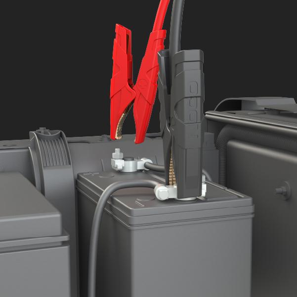

ATTACH CLAMPS.

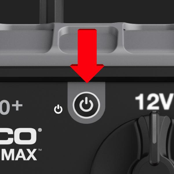


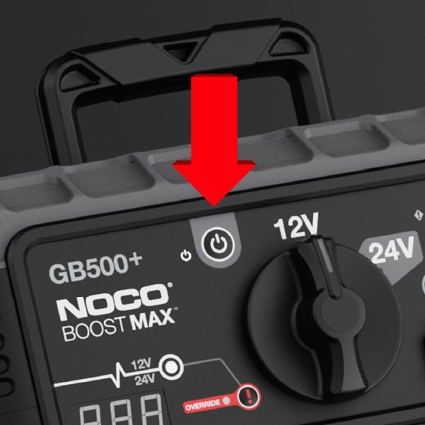
POWER ON.


START VEHICLE.
Within 60 seconds.


Power off.
Or power off/on to reset.
GB500+
LEDs


Power LED
Illuminates White when unit is "on".

Voltage Indicator
12V illuminates White when in 12V mode, 24V illuminates Blue when in 24V mode.

Error LED
Illuminates Red if reverse polarity is detected.

Hot / Cold LED
Illuminates solid or flashes Blue when internal temperature is too low. Illuminates solid or flashes Red when internal temperature is too high.

Charge LEDs
Indicates the charge level of the internal battery.

Boost LED
Illuminates White when Boost is active. LED flashes White when Manual Override feature is active.

Manual Override LED
Illuminates solid Red when Manual Override is activated.

USB Out & 12V In/Out
Illuminates White; USB Out can be used in 12V and 24V modes. 12V In/Out function can only be used in 12V mode.
GB500+
Buttons

Power Button
Push to turn unit "on" and "off".

Manual Override
To enable, push and hold for three (3) seconds. WARNING: Disables safety protection and manually forces Boost "On". Only for use when a battery is too low to be detected.

Light Mode
Toggles the ultra-bright LED light through 7 light modes: 100% > 50% > 10% > SOS > Blink > Strobe > Off
60 Second Timer
Voltmeter will display timer. After 60-seconds, remove the clamps from the Car Battery or power the unit 'off' and back 'on' again to jump start.

Voltmeter
The built-in voltmeter reads the voltage of the vehicle’s battery for enhanced diagnostics and troubleshooting. It will display the 60-second timeout countdown.
GB500+
Troubleshooting
Error
Reason/Solution
Solid Red
Reverse polarity detected. / Reverse the battery connections.
Single (1) Flash
Short Circuit detected on battery clamps. / Remove all loads, reconnect clamps to battery.
Triple (3) Flash
Internal master switch failure. / Ensure the voltage selection knob is correctly positioned in the 12V or 24V position.
Quadruple (4) Flash
Bad battery cell detected during charge. / Power off unit, contact NOCO support.
Quintuple (5) Flash
XGC OUT overcurrent error. / Remove load from XGC OUT, then Power “Off” the unit then power “On”.
GB500+
COMPATIBLE ACCESSORIES.
The following accessories are compatible with the selected product.


Cookies On This Site
Our website uses cookies, pixels, and similar technology (“Cookies”) to make the website work and to improve your online experience. Cookies that are essential for the functioning of our website are always active and cannot be turned off. With your consent, however, we may also use non-essential Cookies to improve user experience, personalize advertisements, and analyze website traffic. By clicking “Accept All,” you consent to our use of all Cookies, including these non-essential Cookies. You may block non-essential Cookies by clicking “Reject,” or change your cookie settings by clicking “Preferences.”
By using our website, you acknowledge this notice, and by clicking “Accept All,” “Reject,” or “Preferences,” you agree to our Website Terms of Use. See our Cookie Policy and Privacy Policy to learn more.